KS0546 Keyestudio 328 PLUS development board

1.Description
Doing experiments with electronic products, we often program on the Arduino IDE development environment with Arduino series microcontrollers.
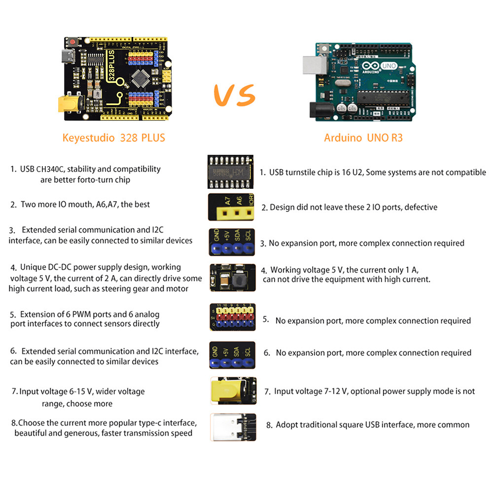
Keyestudio 328 PLUS control board is fully compatible with Arduino IDE development environment. It is as same as the Arduino UNO R3 board. Moreover, some improvements we made highly strengthen its function(as shown below). In order to wire efficiently, we equip it with a 1m USB cable with type-c interface for you.
2.Specification
Microcontroller:ATMEGA328PB
USB to serial chip: CH340C
Working voltage: 5V
External power: DC 6-15V (recommend 9V)
Digital I / O pins: 14 (D0-D13)
PWM channel: 6 (D3 D5 D6 D9 D10 D11)
Analog input channel (ADC): 8 (A0-A7)
Each I / O Port of DC output capability : 10 mA
Output capability of 3.3V port: MAX150 mA
Flash Memory: 32 KB (of which 0.5 KB is used by the bootloader)
SRAM: 2 KB (ATMEGA328PB)
EEPROM: 1 KB (ATMEGA328PB)
Clock speed: 16MHz
On-board LED pin: D13
3. Interfaces
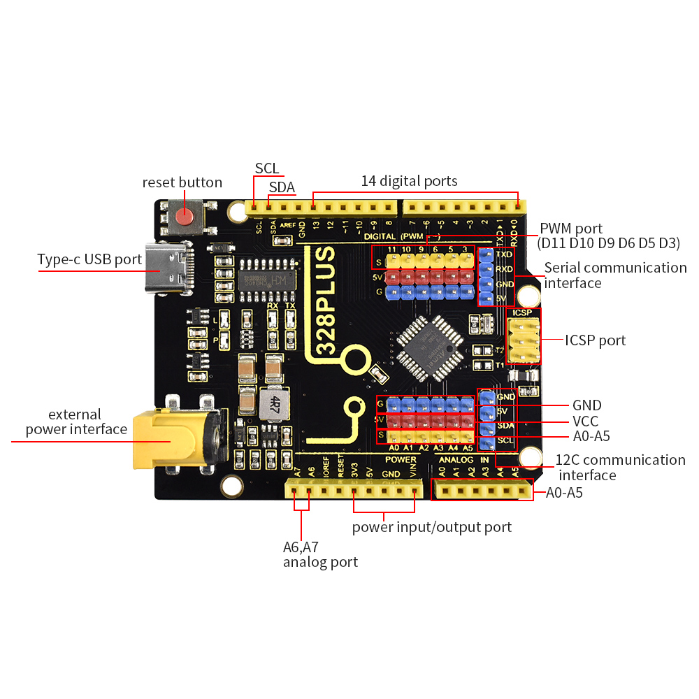
4. Specialized Functions of Some Pins:
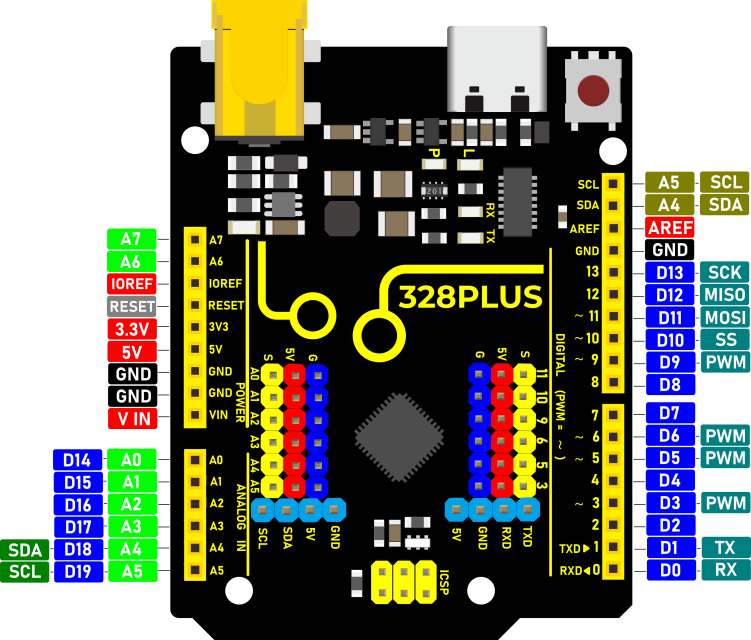
Serial communication interface: D0 is RX, D1 is TX
PWM interface (pulse width modulation): D3 D5 D6 D9 D10 D11
External interrupt interface: D2 (interrupt 0) and D3 (interrupt 1)
SPI communication interface: D10 is SS, D11 is MOSI, D12 is MISO, D13 is SCK
IIC communication port: A4 is SDA, A5 is SCL
5. Install Arduino IDE and Driver
5.1 Download the Arduino IDE
When getting this control board, we need to install Arduino IDE.
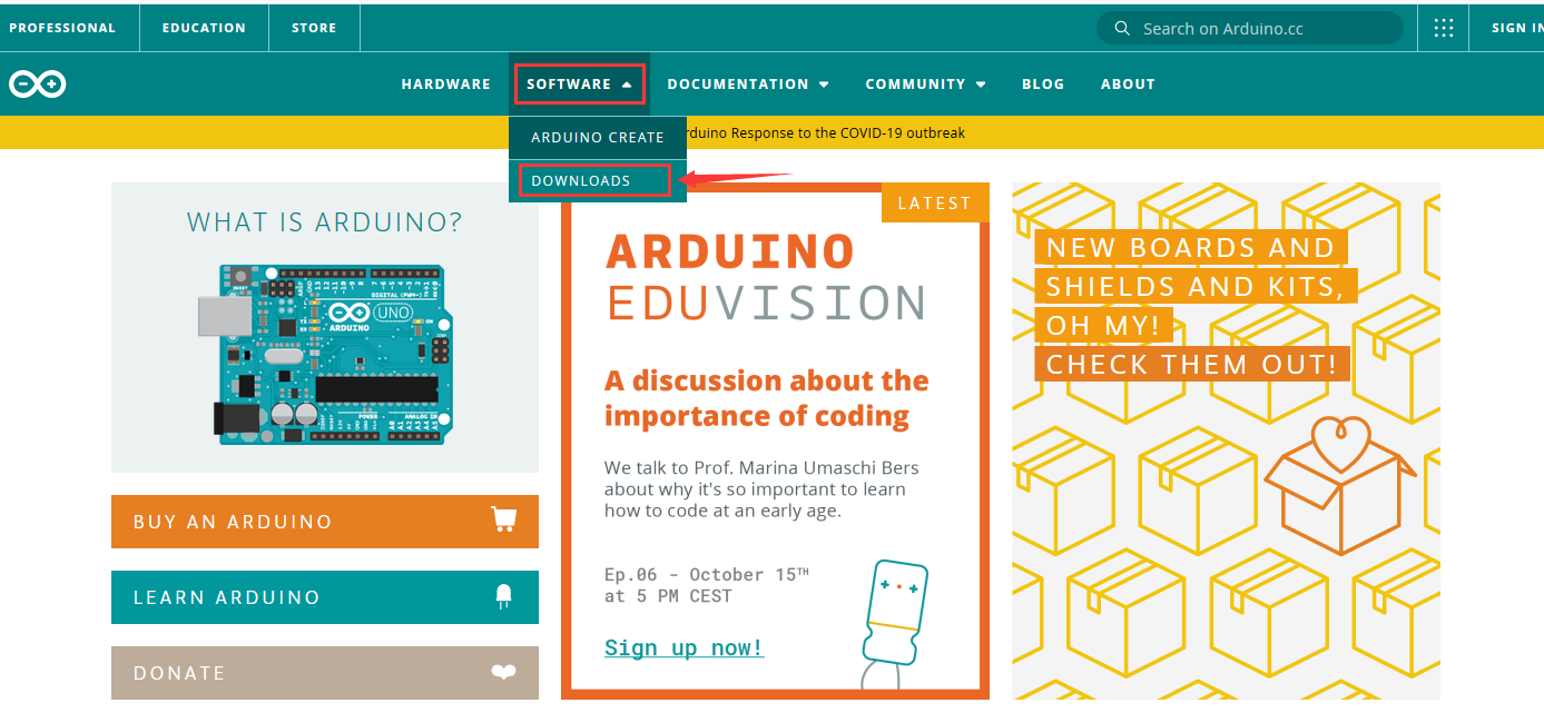
Enter the website
https://www.arduino.cc/,click and
and
Download the version you want and the latest one is available for downloading too.
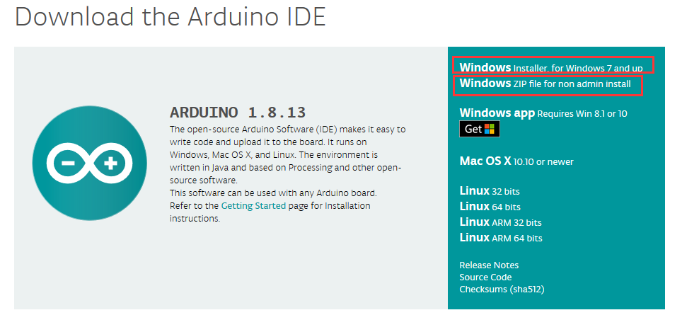
Alternatively, you could select previous release.
In this project, we use 1.8.12 version
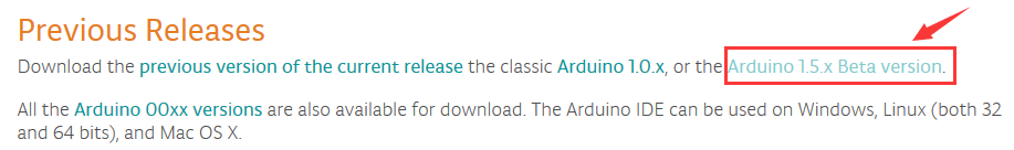
Click  to view the below page
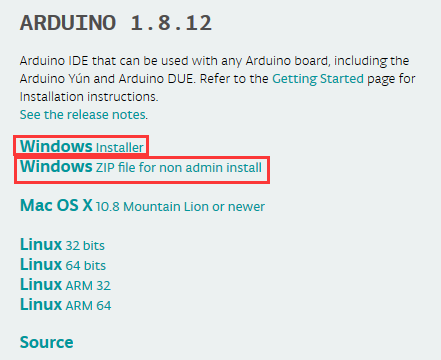
Click  to download an installer
of Arduino 1.8.12 version,which needs to be installed manually. When you
tap
to download an installer
of Arduino 1.8.12 version,which needs to be installed manually. When you
tap ,a zip file of Arduino 1.8.12
version will be directly downloaded, and you only need to unzip it to finish the
installation.
,a zip file of Arduino 1.8.12
version will be directly downloaded, and you only need to unzip it to finish the
installation.

Click icon to download Arduino
IDE.
to download Arduino
IDE.
5.2Installing Driver
Windows system
Download CH340 driver:
https://sparks.gogo.co.nz/ch340.html
Next, let’s install Arduino driver.
For different operating system, there may be slight difference in installation method. Below is an example in WIN 7.
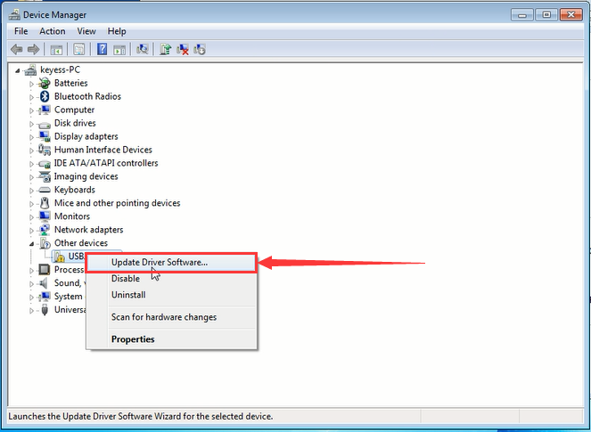
When you connect Arduino Uno to your computer the first time, right click “Computer” —> “Properties”—> “Device manager”, you can see “USB2.0-Serial”.
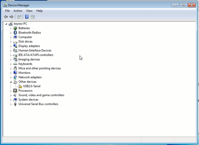
Click “USB2.0-Serial”, select “Update Driver software”.
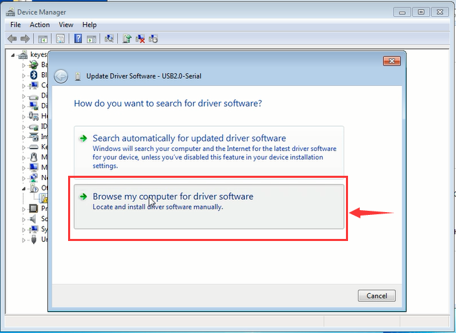
In this page, click “Browse my computer for driver software”.
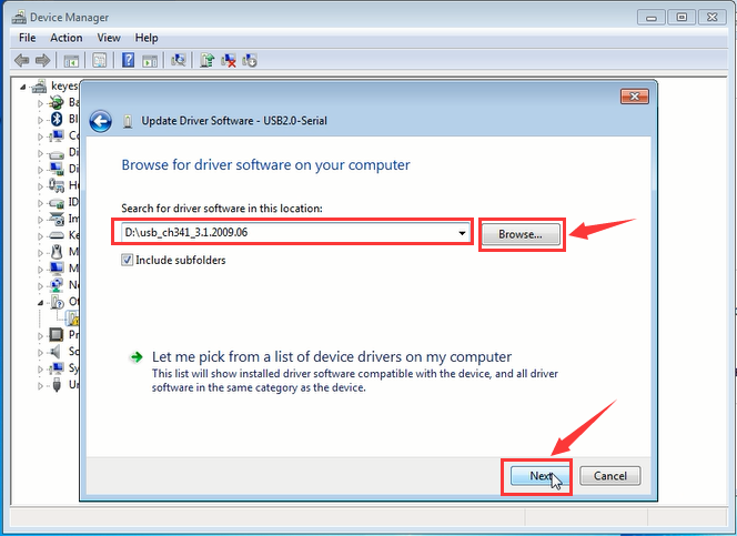
Find the “usb_ch341_3.1.2009.06” file,Click “Next”.
Installation completed; click “Close”.

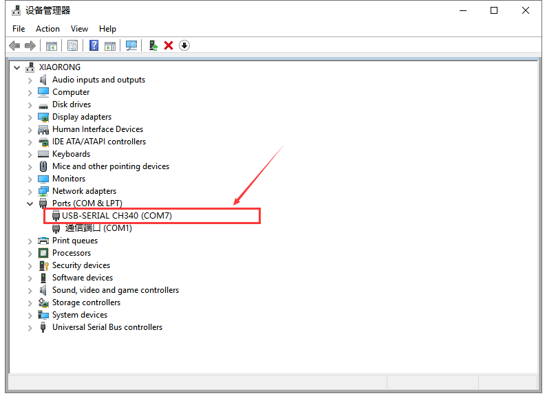
After driver is installed, go to “Device manager” again. Right click “Computer” —> “Properties”—> “Device manager”, you can see CH340 device as below figure shows, also the Com port info.
2.MAC system
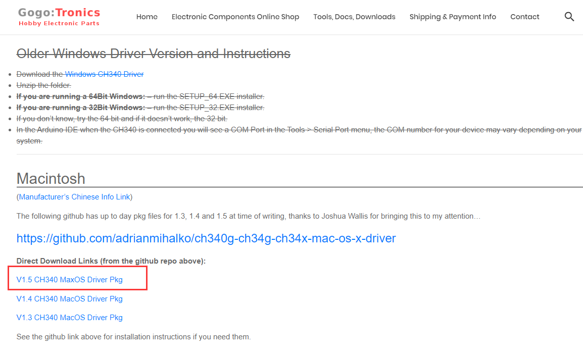
Download CH340 driver:
https://sparks.gogo.co.nz/ch340.html
Click V1.5 CH340 MaxOS Driver package
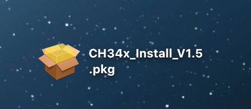
After the download, seen as below:
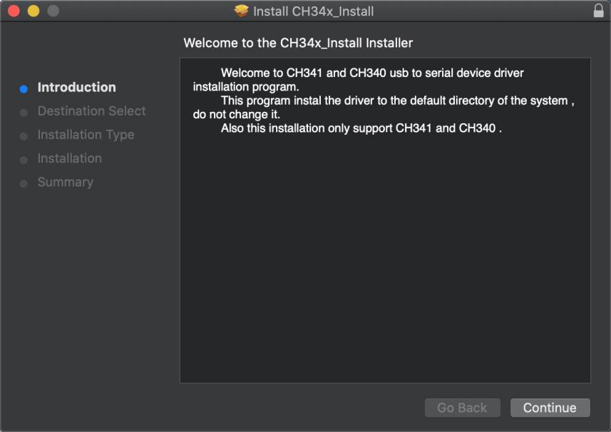
click installation package and tap Continue
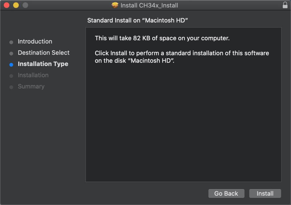
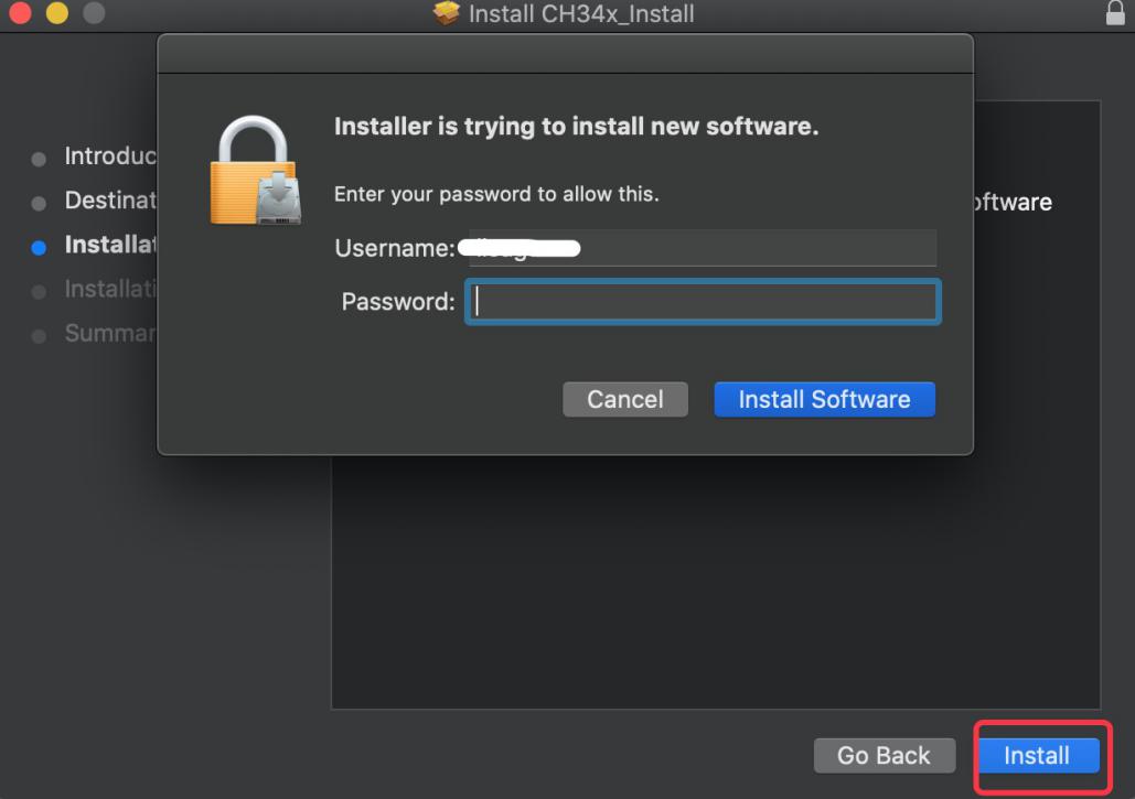
Click Install
Input your user password and click Install Software
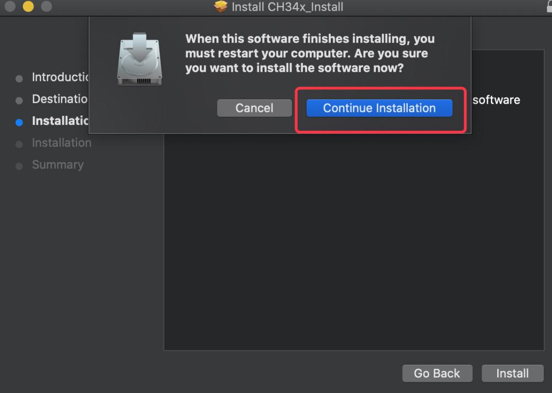
Tap Continue Installation
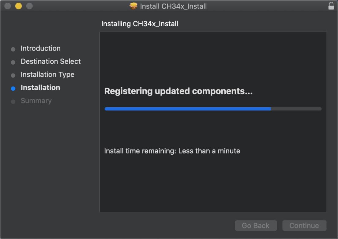
Wait to install
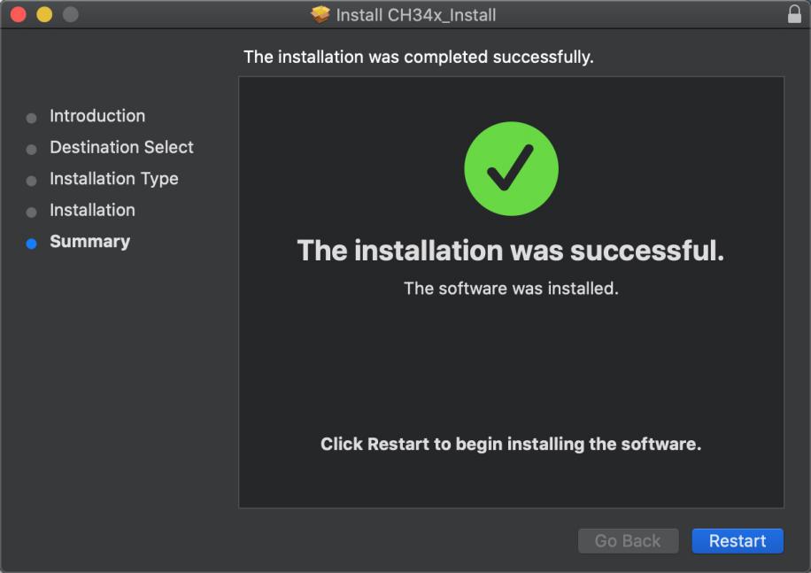
Click Restart after the installation is finished
5.3 Arduino IDE Setting
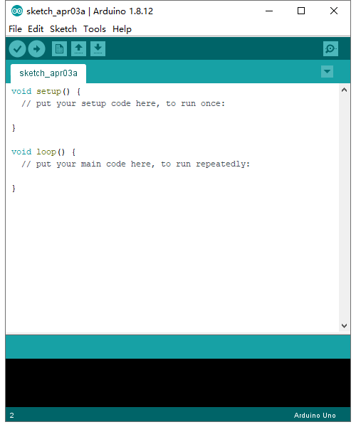
Click icon,open Arduino IDE.
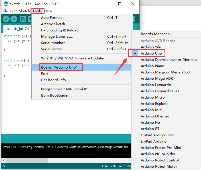
To avoid the errors when uploading the program to the board, you need to select the correct Arduino board that matches the board connected to your computer.
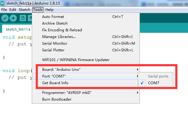
Then come back to the Arduino software, you should click Tools→Board, to select the board. (as shown below)
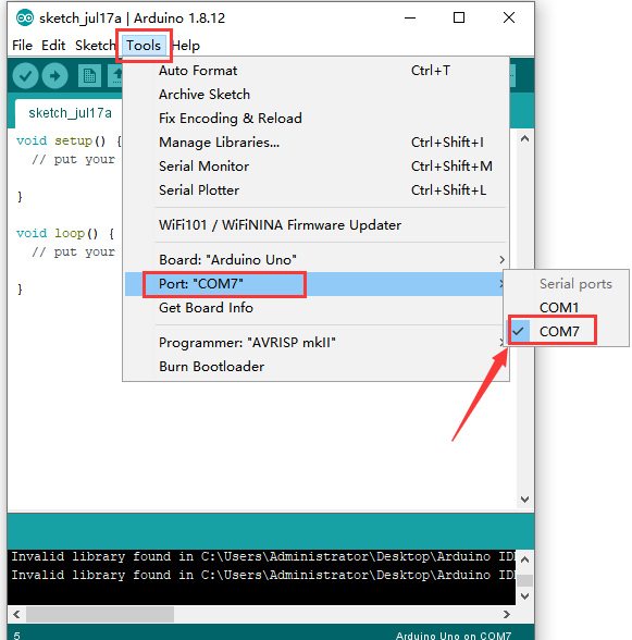
Then select the correct COM port (you can see the corresponding COM port after the driver is successfully installed)
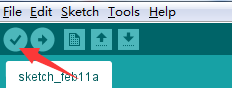
Before uploading the program to the board, let’s demonstrate the function of each symbol in the Arduino IDE toolbar.
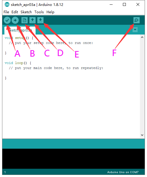
A- Used to verify whether there is any compiling mistakes or not.
B- Used to upload the sketch to your Arduino board.
C- Used to create shortcut window of a new sketch.
D- Used to directly open an example sketch.
E- Used to save the sketch.
F- Used to send the serial data received from board to the serial monitor.
5.4Start First Program
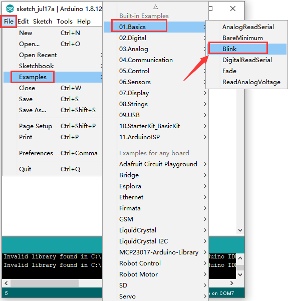
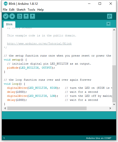
Open the file to select Example, and choose BLINK from BASIC, as shown below:
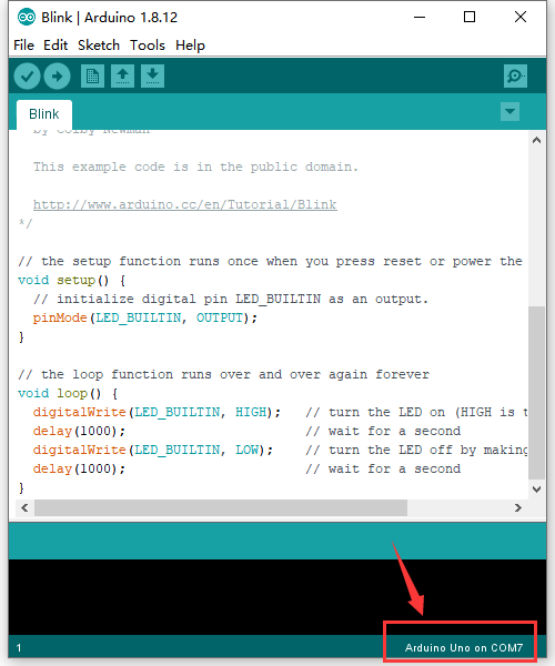
Set board and COM port, the corresponding board and COM port are shown on the lower right of IDE.
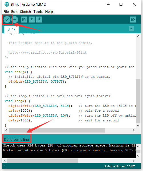
Click to start compiling the
program, check errors.
to start compiling the
program, check errors.
Click to upload the program,
upload successfully.
to upload the program,
upload successfully.
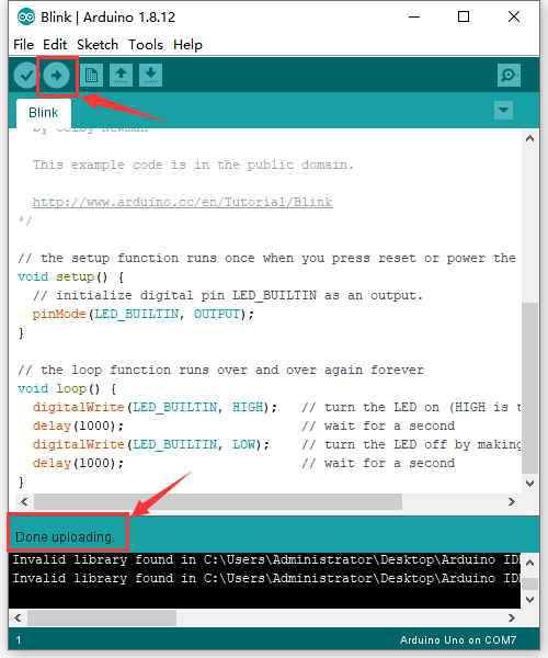
Upload the program successfully, the onboard LED lights on for 1s, lights off for 1s. Congratulation, you finish the first program.
6.Troubleshooting:
1.If test code can’t be uploaded,
click
However, if clicking (verifying
test code) doesn’t work, there is something wrong with the test code or Arduino
IDE.
2.If test code can be verified but not be uploaded, check the correct development board or COM port you choose.
3.If you can’t select the correct COM port, just check if the driver of the development board is installed successfully.(refer to 5.2)
4.Since unstable power supply from USB, you can change different USB ports if the development board can’t be recognized.
5.When uploading test code, TXRX of the development board is not allowed to be used(fail to upload test code).
If the Bluetooth module is used, upload test code then install the BT module